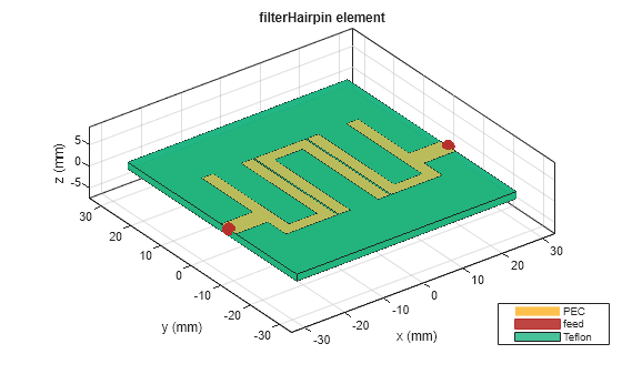
This example shows how to design and analyze Hairpin filter in RF PCB Toolbox. Fill in the parameters as desired.
Design Example Nuhertz On Dms Hairpin Filter Youtube
Parameter for hair pin band pass filter the physical dimension of hairpin filter are determined by using full wave EM simulation IE3D Zeland software.
. The filters application is image rejection at the input of a synthesized block downconverter. Hairpin filters are an interesting topic for microwave designers. The filter synthesis window will open.
B Filter Design Specification- 1 Center. The response of the proposed filter is shown in fig4. This video demonstrates a rapid and accurate flow for designing microstrip cross-coupled filters using Nuhertz filter solutions and NI AWR Design Environment.
First you select filter typeBPFLPF then select filter realization typeMicrostrip stripline. Design of microstrip five pole hairpin multi bandpass filter. The Coupling coefficient and Quality Factor can be calculated as 2a 55a 2b 55b 2c For i1 to n-1 55c III.
At the top menu under Tools click Filter synthesis. 1 The first step is to select an appropriate low pass prototype. How to design a filter on microstrip patch antennas.
Design of conventional hairpin filter Hairpin line filters are compact structures. DESIGN OF THE HAIRPIN BAND PASS FILTER A The design of band pass filter involves two main steps. DESIGN METHODOLOGY A microstrip hairpin bandpass filter is designed to have a fractional bandwidth 20 or FBW 02.
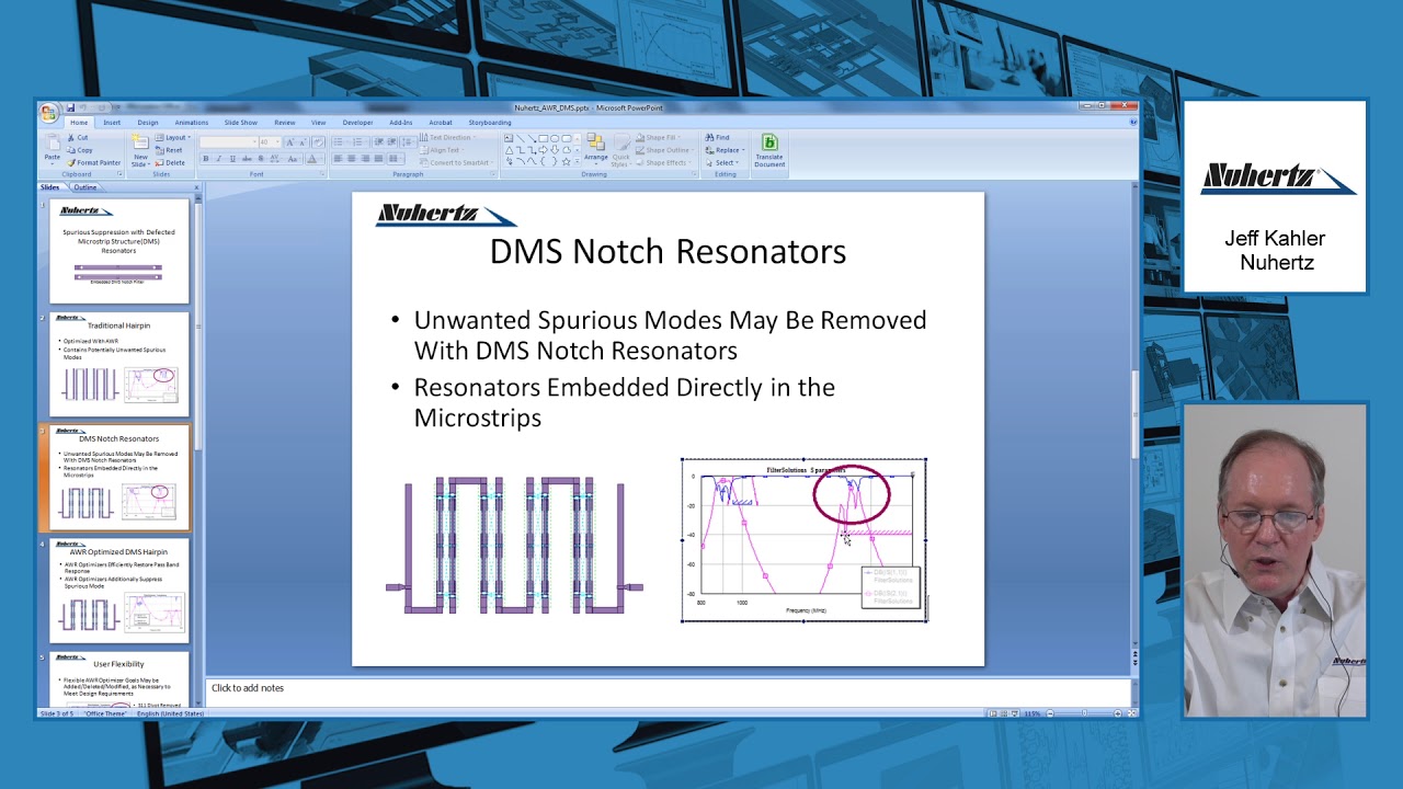
Ifilter can be opened in wizard branch in project tab in AWR. In this article 1GHz Hairpin type of BPFBand Pass Filter design is explained. The simulation results of the filter reach the design goals.
You can click the Generate Design button to see the filter synthesized. The hairpin topology is a microstrip band-. Hairpin band pass filters MHBPFs.
Planar filters can be used to fulfil this purpose. For our example we are doing an LC filter Pi type where the first branch is a shunt Bessel type Low pass Third order scroll down to the Example for mathematical info and a corner frequency of 1 GHz. Hairpin filters for the no-tune transverters 2.
Schematic of the microstrip hairpin. When you want to know more information use a service or make a purchase visit the website you want it is the best way for you. The layout is automatically created.
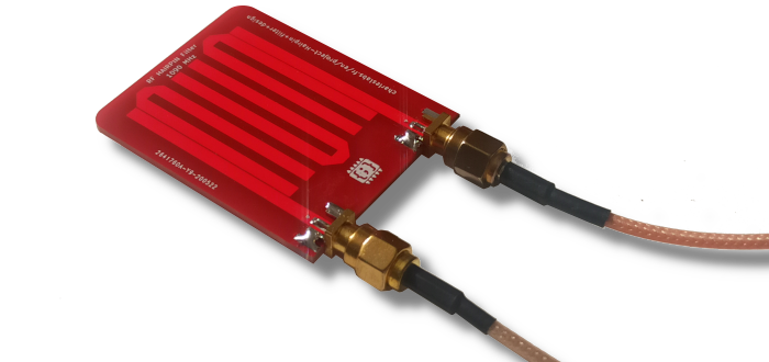
The initial design was entered by schematic cap-ture in the Serenade desktop shown in Figure 1 using Harmonicas microstrip distributed ele-ments library. Design simulation and construction. Hairpin filter topology was used to provide a bandpass response centered at 26 GHz with a 3 dB bandwidth of approximate-ly 280 MHz.
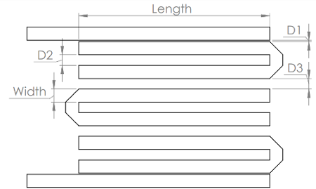
To allow for bending a sliding factor is introduced. A 37 to 42 GHz hairpin filter This filter was designed for a flat response over the 37 to 42 GHz band with low inser- tion loss and return loss better than 16 dB across the band. In this case the corner.
Table 2 gives a comparison be-tween different research works. The figure depicts RF simulation circuit for 1GHz Hairpin BPF. Passband Insertion Loss -3dB or better.
No Our mission is to provide you with information related to Design Of Hairpin Rebars Calculations in addition we also provide you with websites related to Design Of Hairpin Rebars Calculations. One can use Agilent ADS or Microwave Office as RF design software tool for simulation and verifying the results. 106 APPLIED MICROWAVE WIRELESS Figure 1.
Design of a microstrip bandpass filter for 3 1 10 6 ghz. 49 170 9160 110 Fax. By folding the parallel coupled half wavelength resonators in to u shape hairpin resonator is obtained.
Design parameters for the hairpin filter. Among planar filters hairpin filters are available in reduced size as compared to parallel coupled line structures. U can use ifilter in AWR to design a hairpin.
Folded microstrip and dgs shrink bpf microwaves amp rf. Hence the hairpin bandpass filter is capable of passing the fre-quencies between range 3910 GHz and 4436 GHz and re-jects all other frequencies. The length and width of band pass filter is obtain by using equation Z 0 50Ω B 377π2Z 0r - - - - - - - - - - - - - - - - - - - - -6 III.
Microwave filter design chp5 lowpass filters ntuemc tw. These planar circuits are widely used in wireless transceivers and other microwave projects due to an easy design process. Figure 1 Printed Hairpin Filter with tapped input and output There are a number of papers in the literature describing design procedures for hairpin filters but they seem to be long on matrix math and short on practical dimensions.
Design tutorials for cavity combline and microstrip filters. 1GHz Hairpin BPF design. A band pass filter is designed to have a fractional bandwidth of 028 at a centre frequency of 25.
49 89 2420 828 101 Mob. 2 The choice of type of response including pass band ripple order of filter and number of reactive elements will depends on the required specifications. Most wireless applications require high quality low cost and compact sized RF or microwave filters.
FIGURE AND RESPONSE OF FILTER Figure1. This makes the design compact. Filter Design and Tuning using CST Studio Suite Franz Hirtenfelder Applications Engineer CST Branch Office Munich Elsenheimer Strasse 55 D-80687 München Munich Germany Tel.
You can see the help about ifilter. The filter design and analysis described in this paper can be used for wireless transceivers as well as for microwave. To see the filter specification in iFilter double-click the stored wizard state iFilter_Hairpin under the Wizards node iFilter Filter Wizard node in the Project browser.
This how to hide router cords tutorial contains affiliate links but nothing that i w Read more. 49 89 2420 828 198 Email. Electronic filters are circuits which remove unwanted frequency components from the signal to enhance wanted ones.
See attached pic That s very easy to use.
Charles Labs Hairpin Filter Design
Charles Labs Hairpin Filter Design

Pdf Design And Simulation Of Hairpin Band Pass Filter For Different Substrate Engineering Research Publication And Ijeas Academia Edu
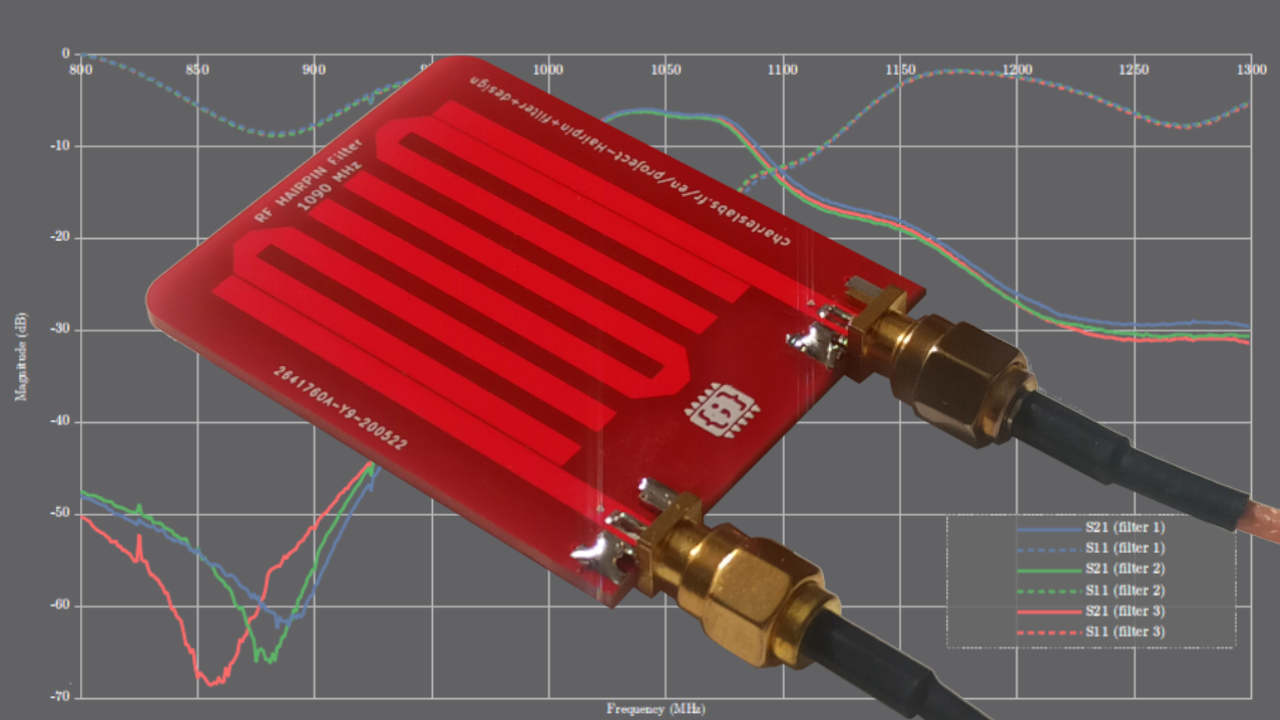
Charles Labs Hairpin Filter Design

Pdf Design Of Microstrip Hairpin Band Pass Filter Using Defected Ground Structure And Open Semantic Scholar
2

Hairpin Micro Strip Line Band Pass Filter Reflectionless Filter Design Simulation Results In Cst Youtube
Design And Analysis Of Hairpin Micro Strip Line Bandpass Filter Matlab Simulink
0 komentar
Posting Komentar